

T60 Reverberator
A PT2399-Based Reverb Pedal

Introduction
Reverb is what I would call an “essential” effect, in that playing without out it doesn't sound quite right. This is due to the fact that whenever we are playing anywhere but an anechoic chamber, there is always some amount of reverberation, or sound bouncing around. In the DIY pedal world, reverb is one of the more challenging projects due to the requirement of producing all those “reflected” sounds.
The two most common DIY reverbs out there are based on either 1) the Belton “brick”, or 2) the Spin FV-1. Both can produce good sounding reverb pedals, but they are each in the ~$20 US range, which is a little steep for a cheapskate like me. So I decided, why build one using such an expensive component when I could spend a bunch more and design something myself? Come on, you know that's half the reason we DIY, admit it...
In addition to the cost, there were other factors that steered me away from the brick and FV-1. With a brick, you have a fixed reverb time (known as T60 in the acoustics world) and no control over the values inside the brick. With the FV-1, there is algorithm development and programming (not a huge deal, but definitely a time vortex risk for me :)), the extra circuitry, etc.
The T60 had a few design goals in mind, namely:
-
No brick or FV-1
-
Use easily accessible parts
-
Provide more flexibility than a brick-based pedal
-
Low parts cost
Some of the projects that I referred to in my R&D phase were the Equinox II from ValveWizard, which uses 2 PT2399 chips, the Belton patent application, which uses 3 PT2399 chips, and Hamuro's spring reverb project from deeptronic.com which uses 4 PT2399 chips. I started with the Equinox II and decided the reverb density wasn't quite what I wanted, so I decided on more PT2399's. Next I breadboarded Hamuro's reverb, but it had never been verified (it was just a theoretical schematic with no actual tuning of delay times, etc.) and it didn't behave the way I hoped. With the Belton schematic, I started there, but built off of it.
Don't care how it works and you just want to build the darn thing?! Well, head right on over here to get everything you need.
How It Works
The T60 is really an extension of the Belton brick. A careful observer will note that most of the architecture is there, but it has been added to with Size, Dwell, and Mode controls along with an extra PT2399 stage that provides the longer reflections necessary to get a room type delay. Let's walk through it.
First off we have an input buffer that gives us a high input impedance and allows us to drive the delay stages with a low output impedance. This is a pretty straightforward implementation using one half of a TL072.

T60 Input Buffer
The buffered, dry input signal is then fed into the first PT2399. You will notice right away that the configuration here is nothing like the typical delay pedal stage. The output opamp has actually been configured as a summing amplifier, allowing the dry input signal and the signal from the mix knob to be summed together with virtual earth summing so that they don't load each other down. This is very important, as without this, turning the mix knob down would actually ground out the input to the reverb stages altogether. The output of this summing amplifier is then fed into the first three PT2399 stages, which act as parallel delay lines.
Also in the first PT2399, you will note the Mode switch and one half of the Size pot. The Size pot serves to increase the delay time on this stage and the third stage (the two longest stages) so that distinct echoes are not heard. Note the presence of R11, which sets the ratio of increase in delay time of stage 1 to stage 3.
The Mode switch bypasses the half of the Size pot on the first stage. Doing this results in a different reverb characteristic that is hard to describe, particularly as the Size control is turned up. You can get distinct echoes back off the third stage in this mode, which can give a fun flavor. Don't want to use it? You can omit it if you like.

T60 First Delay Stage
The second delay stage is also set up a little differently from a typical delay stage. The output opamp of this stage is used as a summing amplifier for the output signal of all delay stages, resulting in an output signal labeled GF for Global Feedback. This provides feedback that gets sent in to each delay stage to help with creating a very dense buildup of “reflections”. Note how it is summed in using the input opamp of the other delay stages.
In addition, stage 2 has a slow, subtle LFO that slightly modulates the delay time of this stage. This modulation helps to create the “reflections” of a large space by not creating perfectly time-aligned delays from this stage. With the LFO omitted, the complexity of the reverb is reduced somewhat. With the LFO up too high, an unnatural warbling sound is created.

T60 Second Delay Stage
The third delay stage is the stage with the longest delay time, though even it starts out as a rather short delay time. This delay time is modified by the Size control, which results in longer delays. In addition to the Size control, there is another LFO on this stage for the same reasons as the second stage, though with slightly different settings that are tailored to this stages delay time. Both LFO's were carefully tuned to produce a rich, complex reverb without unnatural sounding modulation. I found that excess modulation on this third stage resulted in a sickening warble and pitch shifting effect that was not desirable. The LFO on this stage is very subtle, but without it, it just doesn't sound quite the same.
One other item you will notice on the third delay stage is the RSIZE resistor. This resistor is not required for the T60, but if you are building a stripped down version, you can replace the Size pot with a fixed resistor of your liking.

T60 Third Delay Stage
The fourth delay stage is an interesting one. Note how its inputs are only MIX_IN and GF, there is no dry signal fed into this stage. This accomplishes a couple of things. First, it results in a pre-delay so that there is a tiny bit of “space” or time before the first “reflections”, which gives the impression of a physical reverberation. Second, it helps create additional density of “reflections” by acting only on the already “reverberated” signals.
Apart from that, it is set up much more like a traditional delay stage, albeit with a very short delay time (basically the minimum for a PT2399 without latching up, around 30 ms).

T60 Fourth Delay Stage
The signal output stage has controls for Dwell, which feeds back to the signal input to the reverb stages, and Mix, which controls how much reverb is added to the dry signal. The output from the Mix control goes into the output buffer, which is also configured as a summing amplifier for the dry and reverb signals.

T60 Output
The LFO architecture is the same for both LFO's in this circuit. This is your very basic triangle LFO with some filtering to approximate sine-ish. I'm only showing one here for the sake of space. Please see the full schematic for the values for both LFO's that I ended up using.

T60 LFO Architecture
The final block is the power section. This is very basic, with 9V coming in and a 4.5V reference voltage for the opamps and 5V for the PT2399 chips. Note that decoupling caps are local to each IC. One thing I did on the first revision that got axed was a series 100R resistor on the 9V line to act as a noise rejection filter. However, with the current that this pedal draws (~40 mA), that resulted in a significant voltage drop and messed with the 5V supply. Don't do it. Be smart, not like me :).
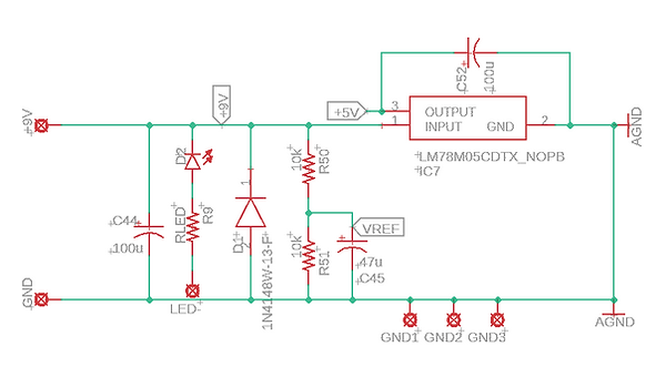
T60 Power Section
In Closing
This is a really gratifying project, knowing you aren't tied down to the man using a brick or FV-1. It's a large circuit, so doing it through hole would likely need a 1590BB, but there are all kinds of possibilities here. I personally am planning to see just how small I can shrink it with just the Mix control. I also am wondering what I could do to take it totally over the top. Please remember that this is for personal, non-commercial use only. I spent a bunch of time and effort on it, so if you do want to use this commercially, let me know so we can find an arrangement. To get the schematic, build documents, and all that good stuff, head on over to my GitHub repository for this project right here. Happy reverberating!
Rev 1.0 Board Notes
If you are using a revision 1.0 of the board (no revision noted by the copyright text), the following items are very important:
-
R7 is not labeled, but is located right above R12
-
R40 and R49 should just be jumpered. With SMD, this can just be solder bridged easily