

Aeronometron
Resonant/Formant Filter With Multiple Control Modes

Overview
Aeronometron is a modulated filter pedal that is really just my take on the excellent Sentient Machine from Parasit Studios. In fact, the audio path is the same as the Sentient Machine because why mess with something that sounds so good? Additionally, the filter topology itself is fairly standard. The real genius of the Sentient Machine is in the use of CMOS switches as variable resistors.
So what makes Aeronometron different? Well, there are a couple of things. First, the Sentient Machine utilizes a rather expensive (~$8 USD) opamp for the LFO generation. This LFO is a modulated high-speed PWM signal and there aren't really any other opamps that have been found to do the same job. When I hear “PWM” and instantly think of a microcontroller (MCU). Microcontrollers are built for providing PWM signals, and creating one at the ~50 kHz used in the Sentient Machine is really quite simple. Also, the part to do so is on the order of $1 and we can use the other I/O of the MCU to do some other cool stuff.
What is this other cool stuff? Well, I included an option for the LFO shape. This can be changed in the code really easily. During development I tried sine, sawtooth, square, random, and triangle LFO's, settling on the sine, triangle, and random for the three shapes. This is all just personal preference, though. Because of the cool sounds of the filter network, I thought it would be fun to have expression pedal control so that you can have essentially a wah pedal that is a formant filter instead of the standard resonant filter. The MCU allows for changing the control voltage from the LFO to expression pedal to something else that I thought was a lot of fun. In my usual perusing of Tayda's offerings, I found a special purpose IC that is a frequency to voltage converter. This sounded like it could be useful for creating frequency-dependent control voltages. In the case of Aeronometron, the speed of modulation is slower for lower frequencies and faster for higher ones.
Another modification on my part is the inclusion of a Voice control. Instead of the toggle to select between the two different filter sounds, the Voice control allows for a continuous blend so that you can dial in the sound you want.
How It Works
At the heart of Aeronometron are two quad opamps that are used for input/output buffering and for the filter generation. In fact, the audio path of this circuit is quite simple, with the genius being in the non-audio sections. The filters are modulated by using the PWM LFO to quickly turn CMOS switches on and off so fast that they end up looking like a variable resistor. The PWM LFO is generated by an ATTiny85.
The input buffer for Aeronometron is a very basic non-inverting opamp stage with unity gain. This is used to buffer and split the signal so that it can go to the various sections of the audio path: dry signal, filter set 1, and filter set 2.

Aeronometron Input Buffer
The first filter bank is a resonant lowpass filter that is created using three opamps. Two of the opamps are modulated using a CD4066 CMOS switch IC as a variable resistor. The CD4066 is switched on and off using a PWM signal at about 50 kHz. This rapid on/off switching acts like a variable resistor. Because the CD4066 has four (4) switches, this allows for the emulated resistances to be very precisely matched. The strength (depth) of the effect is governed by the resistance along the VREF bias voltage to the opamps. The points A1, A2, B1, B2 indicate the connection to switch A and B, respectively, of the CD4066.
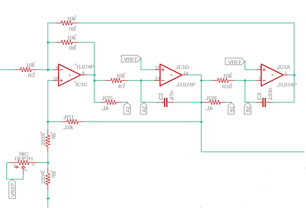
Aeronometron Filter Bank 1
The second filter bank is set up in such a way that, when modulated by an out-of-phase version of the LFO and added to filter bank 1, it creates the formant filter. This changes the tonality of the filter effect and gives it a bit of a robotic sound that seems to sound like “yow-yow-yow”. The voice control is a mix level control for this filter stage so that the end filter result can be dialed in to taste. The C and D CMOS switches are used in two of the three opamp filter stages in this filter bank.

Aeronometron Filter Bank 2
The last part of the audio signal path is the output buffer. This is set up as a summing amplifier for combining the signals from dry, filter bank 1, and filter bank 2. This is a fairly standard topology, so not much else to say about it.

Aeronometron Output Buffer
While the audio path seems fairly simple, there is a lot else going on that makes the effect actually work. First up, we'll just briefly touch on the power section. We have 9V in, polarity protection, 5V regulation, filter caps, and a voltage divider for our reference voltage. However, we also are using an opamp to buffer the VREF signal to help keep it very stable (and because there was an extra one available).

Aeronometron Power Section

Aeronometron Vref Buffer
The LFO generation is handled by an ATTiny85 MCU. This MCU has a switch for selecting the LFO shape, which can be changed in the code by the user. I currently have mine set up as sine by default and then square and rising sawtooth for the other options. I might go with random and triangle instead, but it's all good fun for now and a simple change in the code.
The speed of the LFO is governed by the voltage on one of the MCU's analog input pins, where a full +5V corresponds to the maximum allowed rate in the code, and 0V corresponds to the slowest allowed rate. The LFO output signal is then produced as a high speed PWM signal.
There is also a switch for selecting the LFO control source. The PWM output of the MCU can be controlled not only by the speed potentiometer, but also by two other sources. First is an expression pedal. The expression pedal acts as a voltage divider for a 5V signal. The returned voltage is then mapped directly to a PWM duty cycle, so that the tonality of the pedal is directly controlled by the expression pedal position. This allows for it to be used like a wah pedal. The other method is using an LM2907 frequency-to-voltage converter IC that is designed for things like tachometers and speed governers in automobiles. I decided it would be interesting to see what could be done with it. It turns out that, when fed with +9V source voltage, the output voltages for guitar frequencies range from about 3V to about 5V, perfect for an input to an MCU. In Aeronometron, this voltage is used to govern the speed of the LFO. This means that lower frequencies, which produce lower voltages from the LM2907, have a slower LFO rate, while higher frequencies have a higher rate, making for interesting effects. Even more interesting is what happens as notes decay, when the overtones die out quicker. This results in the LFO slowing down even more as the notes decay. A very fun way of using a chip for something other than its intended purpose.

Aeronometron MCU Configuration
After the PWM signal is produced by the MCU, it gets utilized in three places: to drive the rate indicator LED, drive the A and B CMOS switches, and as the input to an inverting opamp buffer. The inverted PWM signal is used for driving filter bank 2 so that the formant filter is created correctly. As you can see, I used an RGB LED so that one color is used as the bypass indicator and another is used as the LFO rate indicator. I used red for bypass and blue for rate, so that it goes from red to purple in time with the LFO.
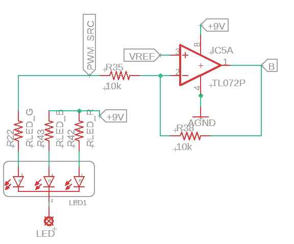
Aeronometron PWM Inversion
The CD4066 is configured to use two switches with the normal PWM signal and two with the inverted PWM signal. By this point, it should be very clear why it's configured like this, but here it is for completeness' sake.
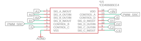
Aeronometron CD4066 Configuration
The final piece of the puzzle is the frequency-to-voltage conversion. This circuit is close to one of the application note circuits in the data sheet. I've changed cap values slightly in an effort to roll off some of the higher overtones. I have also put in a trimmer pot for setting the max output voltage to the MCU. This can either bias all the LFO speeds lower or it can also be used to prevent overvoltage to the MCU. I found that with the highest notes on the guitar, the voltage peaked around 6V or so. In my pedal I actually have the trimmer backed ever so slightly off to prevent peak voltages above about 5.3V or so.

Aeronometron Frequency-to-Voltage Conversion
And there we are! It's a really fun project and a great way to marry digital control with analog signal processing. If you want to make one of your own, you can reach out to me for a board and pre-programmed MCU, or you can find everything you need to make your own here. Happy building!