

Sustainer Driver
A Proven Design for Reliable Sustaining
Overview
Whether you are using a Sustainiac Stealth clone or my FRMT circuit, a good circuit is only half the equation. Without a good driver coil design, the best circuit in the world won't do you much good. The driver design that I present here is not original; rather, it is my implementation of the Sustainiac Stealth driver using the observations and measurements posted on the reverse engineering page. The intent of this page is to provide well documented instructions for making a driver that will work with either circuit I have here on my page so that anyone interested can make their own.
Additionally, I have information on two different circuits that can be used in conjunction with the driver so that it may be used as a pickup when the sustainer is not in use. One design is super simple but its output cannot be combined with other pickups while the other circuit is a little more complex but allows the output to be combined with other pickups in the traditional way.
How It Works
The driver coil takes the output signal from the sustainer circuit and creates an electromagnetic field that induces sympathetic vibrations in the guitar strings that are in its field. To make this driver coil, you will need the following materials.
Required Materials
- Coil Bobbins x2
- 30mmx15mmx3mm or 1x1/2x1/8" N52 Neodymium magnets x2
- 0.85"x0.625"x0.187" steel slugs x2
- 28 AWG/0.3mm enamel coated magnet wire ~38m
- Baseplate x1
- Magnetic steel U-shaped brackets x2 (recommend .024-.03" thick material)
- 2 conductor wire (2 conductor shielded wire recommended)
- Material for potting (epoxy or casting resin recommended, wax is ok as long as you are careful)
- Pickup style driver cover with steel pole toppers
- Copper shielding tape
Optional Materials
- 3.5mm and 6mm heat shrink tubing
- Pickup tape
The first order of business is to wind the coils. The size of the coils is approximately 1.25"x0.625"x0.625". Using bobbins is highly recommended. You can download the .STL file for my bobbin design here to have them 3D printed. I also occasionally have some on hand for sale for rather inexpensive as a way to recoup a small portion of the costs of developing the sustainer projects.
Winding the coils can be done with whatever you have. My first prototype coils were wound using a tape measure and my two hands. You want to put 18.5m of wire on the bobbin in order to reach the 4 Ohm coil resistance. If you are using my bobbin design, it will work to be somewhere around 250 winds, depending on how tight the pattern is. It is important to measure out the wire first, leaving a couple inches on either end of the coil for soldering to the lead wires.
Below is a picture of how I made a simple jig for winding coils. I used a piece of steel cut the same size as a slug that I drilled for a #6-32 screw. I then drilled and tapped a #6-32 hole in a piece of scrap plastic rod. I connected the two using some red Loc-Tite. Note that the connecting threaded rod only goes about halfway into the steel. A shortened #6 screw and waser is us used to secure the bobbin onto the jig so that it is held steady. I also created an .STL file for a 3D printable version (link above). You will still need to tap the hole for a #6-32 (or nearest metric equivalent) for a fastening screw.

Bobbin Holding Jig
Bobbin Mounted in Holding Jig
There are two big advantages to using a jig like this. The first is it can be mounted into a drill chuck or similar and winding can be done faster and more repeatably. The second advantage is that, if winding by hand, it will help save your hand from cramping so badly. In fact, it can be mounted in a small vise or similar, which will result in more control and a better looking coil.
I mounted my jig in the chuck of my metal lathe. This setup is similar to how I wind pickups. The bobbin spins in the chuck while the wire is passed under a polished steel rod that helps provide an even tension on the wire. Wire stops are on the rod to keep the wire from accidentally jumping the end of the bobbin. A magnet placed on the lathe chuck passes under the proximity sensor that is on the headstock of the lathe which is connected to a counter to count the number of winds. If you pre-measure your wire (which I strongly recommend), then keeping count of winds is unnecessary.

Bobbin Winding on the metal lathe
The coil is wound with the lathe on a relatively slow speed so that I can keep good control of the winding pattern. Before turning the lathe on, fasten one end of the wire on the end of the bobbin. Mark this as the bottom side. It's very important to keep track of the top/bottom and start/finish winds of your coils! Once the coil is wound, fasten the other end of the coil to the bobbin with tape and make sure that it is labeled as top.
This wire is much thicker than pickup wire and can handle more tension, but also requires more firm guiding control.

Machine Wound Driver Coil
Now it is time to wind a second coil. The coils in the driver are reverse wound/reverse polarity. This is critically important, so make sure that you label the bottom and top ends appropriately, but wind the second coil in the reverse direction of the first. I did this by changing the rotation direction on my lathe, but I also did it by hand on earlier prototypes by simply winding in the opposite direction.
Once you have both coils, use a razor blade or 400 grit sandpaper to scrape the enamel off of the end of each wire end to expose bare copper. Measure your coils' resistance using a multimeter to verify correct value.

Pair of Coils with Windings Marked
The next step is to glue the magnets into the U-shaped brackets. The brackets help reduce the magnetic circuit reluctance, which basically means that they help create a really robust magnetic field for exciting the string.
Because the two coils need to be reverse wound and reverse polarity, the magnets need to have opposite magnetic poles facing upward. The easiest way to ensure this is to set the magnets side by side and let them stick together on the narrow edge. This will ensure that one has a north pole facing up and one has a south pole facing up. Use a marker to indicate the faces that need to face the same direction in case one of them flips.
Once you have identified that faces that will face up, use super glue or epoxy to glue the magnets into the brackets. I recommend putting the glue in the bracket, sliding the magnet in so it doesn't stick to the side walls first, and keep a paper towel handy, as a mess will be made. Make sure that the magnets do not overhang the ends of the brackets.

Magnets Mounted to Brackets
Next we will glue the brackets/magnets onto the base plate. We want the inner edges of the brackets to be aligned with the inner edges of the white rectangles on the base plate. For single coil-sized base plates, we want the bracket centered vertically on the base plate as well. It should be just narrower than the base plate. For humbucker-sized base plates, we want the top edge of the bracket to not exceed the top edge of the white rectangles so that there is sufficient clearance for the cover mounting lip.
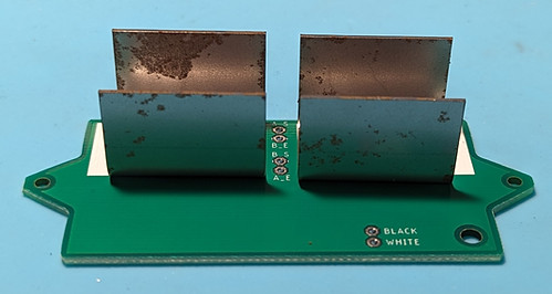
Brackets Mounted to Base Plate
Next up is critically important step: potting the coils. Failure to do so will result in the coils vibrating, causing audible noise, interference, and reduced sustainer performance. For potting, I used a pot of hot water under a metal bowl filled with paraffin wax, but an epoxy casting resin is also an option (I don't recommend regular epoxy, as it is too viscous to penetrate the windings).
If you choose to pot with hot wax, please make note of these lessons I learned from making a ton of these:
- Do not pot bobbins made from PLA, resin, etc., with hot wax. The bobbins will warp badly, as was the case for my first prototypes.
- Twisting the two bobbin wires together makes a convenient handle for holding while potting coils
- If using bobbins made from nylon (such as what I provide in kits) or other high temperature capable material, allow the coil to sit in the wax until bubbles stop coming out. Rotating the bobbin occasionally allows for air to escape from different parts of the coil more easily.
- Once the driver and wax have cooled, scrape off all excess wax from the top and bottom of the coils. I recommend scuffing the surface with some sandpaper (150 grit works well) to remove wax and give the surface some "tooth" for gluing on the pole toppers later.
- Use the steel cores to clean wax out of the rectangular bobbin hole
If you choose to pot with epoxy casting resin, please make note of these lessons I learned:
- Regular hardware store epoxy is too viscous to penetrate the windings and will not adequately pot the coils.
- Warm up the resin at first. This will make it less viscous so that it will really get in there. I used a technique known as "Texas garage in the summer" to make mine nice and thin. As it cools and thickens, you can apply that to the outer windings and it works well.
- It will take a while unless you made yourself a mold, which I did not do. I spent a solid half hour applying resin, waiting, turning, applying resin over and over.
- It will make a mess. Ain't no way 'round that.

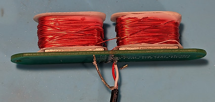
Coils Ready to Be Potted
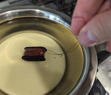
Coil Being Potted; Note Air Bubbles
After the coils have been potted and cleaned up, we are ready to start assembling the driver. Start by inserting the steel cores into both bobbins and scrape the bobbin wire where it will pas through the solder pads on the base plate. This helps avoid issues of the enamel coating not burning away well. Some wire brands have tougher coating than others, so it's a good practice, just to be safe.
Put the bobbin wires for one bobbin through the solder pads and pull through just enough that the wire can be bent at 90 degrees to keep it from coming out
Preparing to Glue In Bobbin
Now apply glue to the magnet inside the bracket and place the coil inside with the flatted edge facing towards the solder pads on the base plate. Align the bobbin so that it is almost over the solder pads in the center and centered top to bottom in the bracket. This will help with the fitting of covers and copper tape application later. After the glue has set for one side, glue in the other bobbin using the same procedure.

Bobbins Glued In
If you are using a PCB baseplate, this is the time when you will solder in your coil wires. How you do so will differ slightly based on whether you will be making a driver with a 2 Ohm total resistance or an 8 Ohm total resistance. The choice will be determined by the circuit you are using. For a circuit like the Sustainiac, the coils will be wired in parallel for a total of 2 Ohms resistance. For a circuit like the FRMT (using an LM386), the coils should be wired in series for a total of 8 Ohms resistance.
For the 2 Ohm case, make sure that the start of one coil is soldered to the end of the other coil and to one of your lead wire conductors. Do the same for the remaining wires. Note that magnet wire is enamel coated to keep it from shorting against itself. Just hitting it with the soldering iron for a few extra seconds usually burns through the enamel, but you can also scrape/sand it off. At this point you should measure the total resistance to ensure that you did it correctly. If using a PCB baseplate, the markings make it super easy to do. If you don't see any resistance reading, it is likely that the enamel coating hasn't been completely removed or burned through.

Checking Coil Resistance
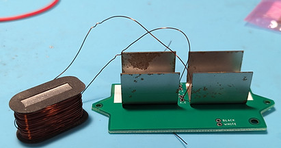
For the 8 Ohm driver case, one coil start wire to one of the lead wire conductors. This coil's end wire should be soldered directly to the start wire of the other coil. If using a PCB baseplate, that means do not connect these two wires to the baseplate. I did this by twisting the two wires together, heating them up for a bit to melt the enamel, and then soldering. I then trimmed the excess. The second coil's end wire should be soldered to the other lead wire conductor. I've tried to show what I mean in this photo.
8 Ohm Driver Wiring
Next, we shield the coil. Shielding the coil helps to contain the driver's electromagnetic field so that there is less chance of it interfering with the bridge pickup. This can be tricky due to the tight tolerance between the brackets and the bobbins. The technique that I found to work best is to remove the tape from the backing (making sure it doesn't curl and stick to itself, which it is very prone to doing), thread the now-empty backing between bobbin and bracket, stick about 1/2" of the tape back onto the backing, and pull it through just enough to get the end of the tape around the curved end of the bobbin. Repeat the process on the other side, but this time you will need to be careful to not let the tape in the U bend stick to itself, but rather make sure it sticks well to the curved bobbin end. Once the tape is all installed, it should be wired to ground. If your lead wire has a shield, solder the shield to the copper tape. Otherwise, run a separate wire that will go to guitar ground.
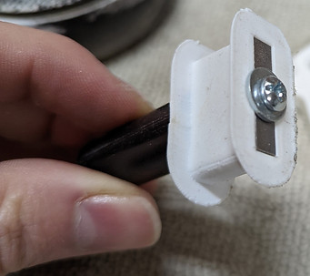
The final step is to install the pole toppers. They function to reduce the magnetic field gap that exists between the two bobbins. This gap is especially problematic for instruments with an odd number of strings. To do this, mount the driver in the cover, apply a small amount of super glue to the top of the steel core, and press the pole topper onto it. Try to minimize any squeeze out so that you don't accidentally glue your cover onto your driver, just in case. I also found it helpful to use one hand to keep the pole cap pressed in place and then to remove the cover with the other hand just enough so that it doesn't get accidentally glued on. Ask me how I know. Go on, ask...

Driver Ready to Have Pole Toppers Installed

Driver with Cover and Pole Toppers Installed
Using a Driver as a Pickup
This question is a topic of great interest to many, since the driver replaces the neck pickup. It is actually quite easy to use the neck driver as a pickup, but there are a few requirements that need to be considered before deciding to go ahead with it.
In order to use the driver as a pickup, the three main things that have to be done are:
-
Disconnect the driver wires from the sustainer circuit
-
Step up the voltage from the driver
-
Account for impedance mismatches with other pickups
The first step is pretty easy. A DPDT switch easily handles the duties of disconnecting the driver from the sustainer circuit and then connecting them to something else. This can be done with a toggle switch, a relay, or any other kind of switch. You just need one pole per driver lead.
The second step is an easy concept, but the actual implementation will have a huge effect on the end outcome. Because the driver is such a low impedance with very few loops of wire, the output voltage will be very low. The best method for stepping up the voltage is using a transformer. Not any old transformer will do, however. The key specs for a transformer include
-
Audio transformer with one side as close to driver impedance as possible
-
25:1 winding ratio (larger is better)
-
High quality core material
You want one side of the transformer with an impedance as close to the driver impedance as possible to minimize the signal loss that comes with impedance mismatches. This means that you will get a stronger signal output than one where the impedance is a larger mismatch.
The winding ratio will determine how much voltage amplification there is. A lower winding ratio will result in a lower voltage amplification. We want as much output as we can get.
A high quality transformer is crucial to getting a good output signal. Lower quality transformers use cheap iron cores that saturate easily and therefore don't produce a clean output signal.
I have found that the Triad SP-48 transformer is an ideal candidate for this task. It isn't cheap, but it's not nearly as expensive as a separate pickup, either. It is super high quality, super small, and the end result is a crystal clear signal.
Once the signal is stepped up, we can use the signal on its own, but if we want to combine it with other pickups, we are going to have issues due to how the other pickups will load down the transformer. Just connecting the transformer output to the pickup selector won't work, and the onboard controls won't work right, either. In order to deal with this, we need some active circuitry. The transformer output needs to be buffered (and optionally filtered to make it sound "right" with the other pickups) as do the other pickups. Once they are all buffered, they all have the same output impedance and won't load each other down and can be combined with a normal pickup selector. Because all the pickups will now essentially be active, you may want to swap out the onboard potentiometers to a lower value.
I have created a simple board that will do both the power switching and the driver lead switching using a super small PCB and a 3PDT toggle switch. The Gerber files for it can be found in the Github link at the end of this page.

Passive Transformer Board for Using Driver as Pickup

Schematic for Using Driver as Pickup
As mentioned above, if we want to use the output of the stepped up driver signal in conjunction with other pickups, we need to buffer the stepped up signal as well as the pickup signals so that they all have the same impedance characteristics and can be used together. A circuit to do just this is shown below. As seen, it is very simple: a buffer with a switchable phase inversion stage for the stepped up signal and two simple opamp buffers for other pickups. Additionally, power switching for the sustainer circuit and buffers is included so that the 3PDT switch acts as the on/off switch for the sustainer.
A couple of brief thoughts about going this route:
- Your pickup output will now be buffered at all times
- The buffer will draw a small amount of power whenever the sustainer is off, so make sure you tie the ground to a switched ground controlled by a stereo output jack on the guitar
- Further info and instructions for this board are found at the GitHub link below in the Documentation folder

Schematic for Active Circuit for Using Driver as Pickup with Other Pickups
There you have it! A reliable, powerful driver coil to use with the FRMT or Sustainiac Stealth circuits. Doumentation and files for the bobbin, base plate, and pickup cover (courtesy of Maurizio Naso) along with the circuits for using the driver as a pickup are available here. If you need help with anything, I highly recommend the Guitar Sustainer DIY group on Facebook, where myself along with many others are active. Enjoy!