

Riptide Spring Reverb
True Analog Spring Reverb

Overview
Reverb is a great effect; it's used almost everywhere. The first portable reverb units were those build into early amplifiers, such as the Fender “Reverb” series amplifiers. Many pedal incarnations seek to capture the drippy, surfy tone of spring reverb through use of DSP, PT2399 chips, or various other methods. However, there is very little that can really substitute for the physical motion of sound through springs. There are nonlinearities and other effects that are very hard to program in DSP and that are impossible to capture with components like PT2399.
A real spring reverb in pedal size is difficult because the springs need physical space to be placed in, along with their corresponding drivers. The reverb tanks found in amps are far too large for pedals, but fortunately Accutronics (makers of most spring reverb tanks as well as the Belton reverb bricks) make a small, two-spring, plastic-encased spring tank for approximately $10 US. At half the price of the FV-1 or Belton brick, it's an attractive option. Keep in mind that springs this small inherently won't have really long decay times, but it gives you plenty of springy goodness that fits in a 1590XX enclosure. In fact, this tank is what Spaceman uses in their $500 Orion spring reverb pedal.
How It Works
Having a spring tank is only part of the equation. The spring tank needs to be driven by our audio signal. Because we are driving a physical transducer, the selection of components such as opamps is more critical, as not any old opamp, for example, can provide enough drive current for the low input impedances of physical transducers. In the case of Riptide, we are driving a 150 Ohm tank, which is like driving a set of headphones.
In addition to component selection, Riptide further taps into the vintage tone profile by using a JFET preamp that gives some great color. It's essentially the Dunlop EP101 Echorec Preamp with a fixed gain, which sounds great and helps lend some of the vintage warmth associated with an old school spring reverb. Note that C2 is adjusted for overall circuit brightness, if desired. As specified, it provides a nice, balanced tone that doesn't go too bright or too dark.

Riptide Preamp
One design choice with Riptide was the ability to have reverb tails. To do this, a J112 JFET is used as a switch for the reverb path, so that when reverb is disengaged, whatever signal is still in the system is able to propagate to the output. This also means that the preamp is always active, which can be great if you like the tone of it. Of course, it can also be wired up as true bypass without a problem. For specific instructions, see the Build Notes section near the end.

Riptide Tails Switching
Next is the tank driver section. This is pretty straightforward and is a pretty bog-standard implementation of the spring reverb driver found on the excellent Elliot Sound website: https://sound-au.com/articles/reverb.htm. The Dwell control determines how hard the tank is driven. Driving it harder introduces more nonlinearities and possibly some saturation of the springs. The use of the NE5532 is critical because of its current drive capabilities. This is also a great opamp for driving headphones, as found in deadastronaut's ASTROSIM cab sim (an excellent project that I highly recommend! https://deadastronaut.wixsite.com/effects/astrosimcabsimulator). I experimented with feedback in the system, but it ran away easily and when it didn't, it still wasn't terribly musical or even pleasant sounding. Note that RS stands for Reverb Send, with the + and – indicating the connections to the reverb tank input terminals.

Riptide Drive Section
Once the signal has been amplified and sent to the tank successfully, the reverb signal needs to be shaped and amplified. The NE5532 is used here as well, though it is probably less critical than the drive stage, but still highly recommended, as that is what I used. R8 and C5 change the tonal response of the output signal, where R9 acts as the gain control of the peak created and C5 determines the frequency of the peak. I played around with various values and found that these sounded quite good. It is possible to replace R8 with a pot to give an adjustable peak gain, but I didn't find it necessary (given the inclusion of a tone control later). R9 is to prevent railing out the opamp if the tank gets disconnected, and R11 controls the overall gain of the recovery stage (in conjunction with R10, do you see the basic non-inverting opamp gain stage structure?). Note that RR stands for Reverb Recovery and the + and – symbols indicate the appropriate connection to the tank output terminals.

Riptide Recovery Section
Now that we have our fully wet signal, we have the final stages which provide the tone and mix controls as well as the summing output buffer to combine the wet and dry signals. The tone control is one I've used before, and is the same architecture as that used in some EQD pedals. It's pretty flexible with a minimal parts count. The summing amplifier/output buffer is pretty standard stuff and, if you've seen any of the other projects, you've likely come across something very similar.
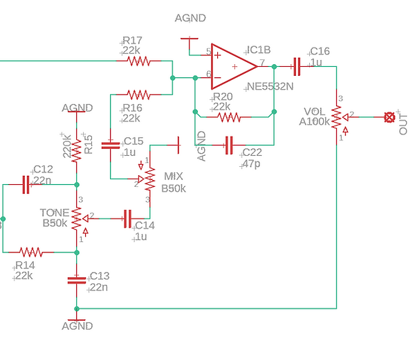
Riptide Tone/Mix/Output Section
The power section provides both + and – 9V so that the opamps can be run at a dual voltage supply. Using the bipolar supply instead of just doubling to 18V allows for the elimination of a few extra passive components.

Riptide Power Section
So there we are! There are plenty of options and things to take into account when building one, so head on over here and get the full build documentation, board layout files, and schematic so that you can make your own. Happy building!