

Rubber Ducky
PT2399 Delay with Ducking
Overview
I love delay. It fills out a soundscape, it adds interest, and in general, it's just awesome. However, sometimes you want nice, strong repeats but they can get in the way of the new notes that you play. That can be desirable at times, but other times you want that big, in-your-face delay repeat but a more present, dry attack. The Rubber Ducky allows for precisely this. It's a straightforward delay circuit with an envelope follower and optical compression of the delay signal so that you can dial in just the right amount of detail for new notes while allowing the strong delay to fill the space between notes.
Ducking of effects using a side chain input is a common studio technique that allows key signals to be more forward in the mix. It gets used on vocals, snares, kick drums, and more all the time. However, this technique is not used much in a pedalboard environment, which I think is a gross oversight. So come on and let's dive in to this deceptively simple circuit!
How It Works
At its most basic level, the Rubber Ducky can be broken up into two parts: a delay effect circuit and an envelope follower/optical compressor. The delay is a fairly standard PT2399-based delay circuit with some values dialed in to taste. The optical compression is based on the scheme used in the venerable Fairchild 603 triggered by a full-wave rectified envelope follower.
The first block is the input buffer. The input buffer is a very standard unity gain, inverting opamp stage. The one thing to note here is that we are using a bipolar power supply. The reason for this is that it makes the envelope follower performance much more consistent. It's a little added complexity and cost, but I feel it is well worth it.
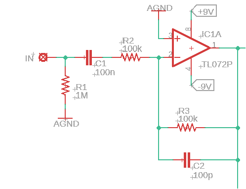
Rubber Ducky Input Buffer
The signal from the input stage is then sent to the delay stage where it functions much like any other standard PT2399 delay. The values were chosen to give a “squeaky clean” (get it?! I'm hilarious...) delay signal (i.e., not too heavy of a filter like some others). The output of the PT2399 has the standard Feedback control, but before the mix control we have the optical compression stage. This is done prior to the mix control so that you can really crank up the mix knob, but still get plenty of attenuation when compressing. If you've looked at the Escape Artist or Disappearing Act, that part will look familiar to you.
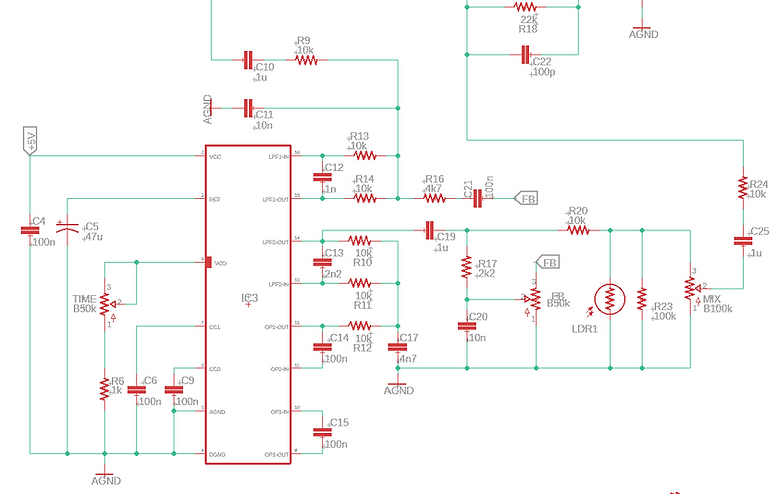
Rubber Ducky Delay Stage
After the delay stage is a basic summing amplifier that also serves as our output buffer. The keen observer will note that the summing resistors for dry and wet are different, allowing for about double the gain for the delay vs. the dry. This is on purpose, so that you can get an obscene amount of delay going and use the ducking action to keep things from getting too soupy. You can even crank up wild feedback and duck it out when playing. It's pretty fun.

Rubber Ducky Output Buffer
Even though we have discussed the audio signal path, we aren't going to have any ducking if we don't trigger the LDR with an LED. To do this, we need an envelope follower of some kind. There are many choices here, but I decided to go with an opamp-based full wave rectifier. This consists of a first amplification stage that boosts the input signal such that we can get a robust rectified voltage at full sensitivity. This is a simple inverting opamp stage with a fixed gain.
After the fixed gain stage, the Sensitivity control is a simple voltage divider before the rectification happens. With the Sensitivity control all the way up, the resulting rectified DC voltage will be strong enough to drive the LED to full or near-full brightness. With the control rolled down, the DC voltage will be low enough so that it won't drive the LED fully. In fact, with the sensitivity control rolled all the way down, there will be no ducking action at all and the Rubby Ducky will just be a normal delay. This is handy if you are doing ambient stuff or something.
The rectification of the signal happens with the second opamp stage using diodes that make is to that voltage swings can't be negative and so that we see a DC signal with plenty of rippling on it. Cap C24 helps to smooth out these ripples, but it also works in conjunction with R19 and the Release control to determine the time constant of the envelope follower. With the Release control all the way up, R19 presents a low-ish resistance path to discharge C24, resulting in a fast time constant and the LED responds virtually instantaneously to signal level changes. With the release control all the way down, C24 discharges more slowly and it takes more time for the LED to dim, resulting in a longer time constant of the ducking action. The LED's are driven by the third opamp stage and are placed in the negative feedback loop. This is what drives the LED's brightness. The LED brightness can be tweaked some by adjusting R21, but if it goes too low, you can burn out the LED by sinking too much current and that's a bad day, trust me. If you really want to tweak the LED brightness, I suggest looking at the first opamp stage.
Note that there are three LED's in the feedback path. Only D8 is used for the optical compression of the delay signal. I added D7 as a visual indicator of how much compression is happening, since doing it just by ear with various guitars can be a little finicky. A visual indicator means you can adjust the sensitivity and release for a given guitar quickly and accurately.

Rubber Ducky Envelope Follower
The final piece to the puzzle here is the power supply section. It uses a DC-DC charge pump IC to produce the +/-9V necessary to run the opamps and produce higher headroom as well as a 5V regulator to power the brick. Nothing else here should be a surprise to anyone.
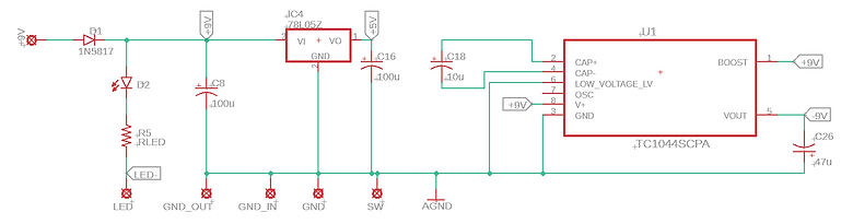
Rubber Ducky Power Section
And there it is, a simple but effective ducking delay pedal! I hope you enjoy it. If you want to make one of your own, you can find everything you need right here.