

Reverse Engineering a Sustainiac Sustainer
A Detailed Look at the Original Sustainiac Stealth
Overview
For many years, I’ve been interested in what are called sustainers. These are devices that allow the guitar to sustain infinitely. They have been used for a long time by the likes of The Edge, Steve Vai, and Ed O’Brien of Radiohead. Being a huge U2 fan, I was first introduced to the effects they provide by listening to With or Without You.
Additionally, sustainers are a fantastic application of physics. The basic principle is this: your string vibrates in the electromagnetic field of your pickup, which results in a voltage. That voltage is then sent to an onboard amplifier, which drives a low impedance coil. This creates an electromagnetic field that then drives the string, resulting in an infinitely sustaining note. It’s a similar concept to feedback from your amplifier, but in the case of amplifier feedback, it’s the moving air driving the string to continue vibrating.
There have been many DIY sustainer projects over the years, with many of the earliest experiments by a guy named Pete who went by the handle psw at the Project Guitar forum some 15 years ago. However, most of the DIY implementations have been plagued with some problems, such as poor drive capability on the B and E strings. Most of these solutions are built around the LM386 amplifier chip with a JFET preamp, basically the Runoffgroove Ruby amplifier. While this is a simple circuit and can be made to work somewhat, it’s not an ideal solution.
There are two main players in the commercial game: Fernandes and Sustainiac. The Fernandes system was developed by a few guys including Floyd Rose, yes, that Floyd Rose. Sustainiac came later, but it also is a well known and well respected name. The main drawback with these systems is that they are expensive. A new circuit/driver combo typically runs anywhere from $250-$400 USD. However, they have features that the DIY ones simply don’t. For example, they have an automatic gain control, or AGC, that adapts the amount of gain the amplifier supplies based on how well the strings are vibrating so that the strings are always driven well. They also have the standard mode, as well as a harmonic mode and a normal+harmonic mode. Some of the DIY circuits have a harmonic mode that just flips the phase of the drive signal so that the fundamental is damped and the harmonics are driven. I am unaware of any DIY setup that has normal+harmonic mix.
I first thought I might design my own circuit from scratch, but came across a second hand Sustainiac system on Reverb.com for a reasonable price. I made an offer and it was accepted, so now I have this lovely system here that I intend to reverse engineer. I’ve never reverse engineered a circuit before, so this will be a learning experience for me.
How It Works
While the basic concept of how a sustainer works is quite simple, the implementation side of things can be quite complex. For example, let's look at the original patent documentation for the Fernandes sustainer, US Patent #5,233,123 (Additional patent numbers given at the bottom of the page). Below is the block diagram of the system. We can see here that we have our bridge pickup, the preamp, some free space compensation, and our guitar amp. We’re not so worried about the guitar amp and speaker, but they are here for completeness. The preamp then feeds three different signal paths, which make up our normal, harmonic, and normal+harmonic or “lead” modes.
The box labeled THRU is the normal mode where it is simply boosting the pickup signal to drive the driver coil. The LAG NETWORK is an opamp based stage that provides a static phase shift, or lag, to the input signal to force the driving of harmonics. Unlike many DIY designs that simply invert the phase for harmonic mode, the inventors argued that a tuned phase lag will actually result in better performance. It’s not overly complex as they show in the patent, but most of the cheapo systems out there ignore it. Finally, there is the VARIABLE LEAD path, which is the normal+harmonic. This is a rather complex piece of circuitry that does some frequency to voltage conversion which then drives a variable resistive element in an amplification network to create the drive signal. There is easily as many components in this section as in the rest of the circuit combined, so it is frequently omitted.
Once the drive signal is produced, it gets fed into an AGC that feeds an opamp gain stage which, in turn, feeds the output amplifier. The output amplifier not only drives the driver coil, but it also feeds the AGC so that the driver signal doesn’t get too large and saturate and so that we can boost smaller signals some.

Sustainer Block Diagram
While the above diagram may be easy enough to understand, the actual circuit gets more complex. Below is the schematic from the patent documentation. As you can see, there is quite a bit going on. Fortunately, the authors annotated it pretty well and it follows the organization of the block diagram.
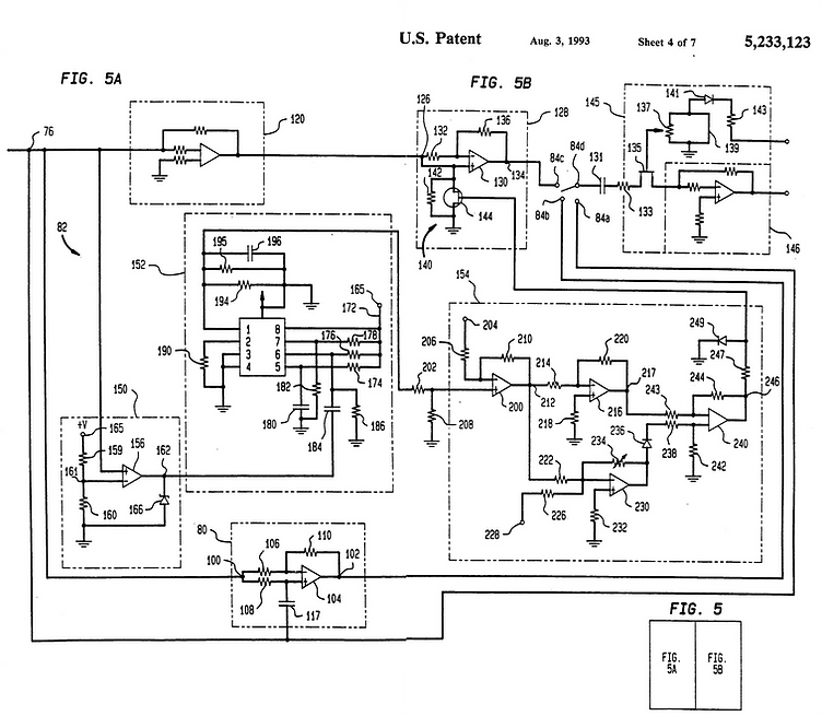
Sustainer Schematic per Patent Documentation
Sustainiac Stealth
When I came across a Sustainiac system on Reverb for pretty cheap I couldn't help myself. My curiosity got the best of me and I ordered it. After receiving it and doing some research, I found that it is an original Sustainiac Stealth unit from 1999. Apparently they only made 100 of these before moving on to the Stealth PLUS model, which was then replaced by the Stealth PRO model in 2008. After correspondence with the fine folks at Maniac Music (who own Sustainiac), I got some wiring diagrams and learned that the primary differences between my unit and the current ones are the use of a monolithic Class D amplifier chip (as opposed to discrete MOSFET class D amp) on the PRO models and the presence of onboard circuitry to allow the driver coil to be used as a pickup. This is fine for me, as I am most interested in the non-power amp happenings.
Driver Coil
Let's first look at the driver coil. Most DIY sustainers use an 8 Ohm coil of 30 AWG wire as the driver. The Sustainiac driver is noticeably different. Let's go through the stages of deconstruction.
Overall driver resistance is 2 Ohms, which is significantly less than the 8 Ohms common in the DIY world. Sustainiac maintain that lower driver resistance allows for greater drive strength. When looking at amplifier specifications, lower impedance loads are able to deliver more power, so it kind of makes sense. The lower impedance also allows for a greater magnetic field strength, which will increase drive strength.
Removing the bobbin tape shows us that the driver is wrapped in copper foil shielding tape and that both the shield and the 1.3 mm thick galvanized steel baseplate are soldered to a wire that will go to ground inside the guitar wiring cavity.

Shielded Driver Coil
Desoldering the ground wire and unwrapping the copper tape reveals two side by side coils that are 0.625" tall. The coils are wound from 0.3mm red enameled magnet wire. This corresponds to somewhere around 28 AWG, a little bit thicker than the standard DIY designs. The driver supply wires are separated so that each coil is wired to + and - and are reverse wound, meaning that one coil is wound the opposite direction of the other.
Examining the magnetic orientation of each coil reveals that they are opposite orientation, resulting in a RWRP configuration, which helps contain the electromagnetic field more efficiently and prevent the driver signal from contaminating the bridge pickup signal.
The coils are wax potted to prevent microphonics and two identical bobbins are used for winding the coils.
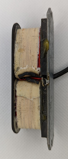
Driver Coil with Shielding Removed
The magnets are ceramic and have dimensions 0.625"x1.25"x0.125". The magnets are epoxied to the baseplate and the bobbins are epoxied to the magnets. The top plate is lightly glued on, along with the .05"-thick steel caps. According to Sustainiac's patent documentation, these caps are made from magnetic stainless steel and are used to reduce the magnetic gap between the two coils. In fact, the more recent drivers that use the angled steel caps are doing so not for aesthetics, but in order to reduce the magnetic "dead space" between the two coils. If a string is bent or otherwise placed in this magnetic "dead space", it won't be able to drive the string. Removing these caps reveals the bobbin core to be laminated steel with dimensions 0.2"x0.85". Once again, the patent documentation states that the cores are made of transformer lamination steel, which allows for much better magnetic field propagation. Cleaning up the tops of the cores revealed 9 total layers: 7 thicker layers and 2 thinner layers. Some great investigation by Maurizio Naso revealed that these are non-grain oriented and grain-oriented steels.

Driver Coil with Decorative Topper Removed
Finally, I desoldered the coil leads and measured the resistance of a single coil. It came in at 4 Ohms, confirming that the coils are RWRP wired in parallel. Further confirming this is the fact that the + wire is the start winding for one coil and the end winding for the opposite, as far as I can tell. I couldn't completely disassemble the driver non-destructively, so I left the investigation off there.
To recap, the key specs are:
-
Driver Resistance: 2 Ohms (two 4-Ohm coils wire in parallel)
-
Coil wire: 0.35 mm diameter, red enamel
-
Base plate: 1.3 mm galvanized steel 3.25" long by 0.7" wide, grounded
-
Magnets: Ceramic, 0.625"x1.25"x0.125", reverse polarity relative to each other
-
Individual Coils: 0.625" tall, wax potted reverse wound relative to each other
-
Coil Core: Laminated Steel 0.2"x0.85"
-
Decorative top: .05" thick steel 0.2"x1.1"
Sustainer Circuit
The sustainer circuit has been something of much debate. Some circuits to drive a sustainer driver coil have been as simple as a single transistor preamp followed by an amplifier IC, like the LM386. Others utilize cutting edge class D circuitry. In order to get good performance across all strings, there are a couple of neat tricks that the Sustainiac uses. Before we get too deep into that, here are some photos of the board front and back, populated and unpopulated. The headers were left in place since connections to them are obvious once all the components are removed.

Sustsainiac Stealth Board - Top

Sustsainiac Stealth Board - Bottom

Unpopulated Sustsainiac Stealth Board - Top
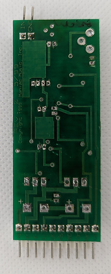
Unpopulated Sustsainiac Stealth Board - Bottom
And now for the good stuff. Before breaking down the schematic, and before I traced the circuit, it is good for us to outline what functional blocks there are in the circuit. Because I didn't know too much of what there would be, I looked to the components for clues. With the large caps and MOSFET's, I figured those would be the power amp. Aside from the power amp, we knew there were 6 opamps, so we likely were using those as gain stages or buffers. The dual comparator threw me for a loop.
I started out by tracing all the signal paths with the continuity setting on my multimeter. From these, I built out a schematic that was electrically correct, but very unreadable and not intuitive. I spent quite a bit of time trying to break it down into functional blocks. Through the assistance of a friend at work and Vivek Mehta from the DIY guitar effects community, I was able to get clarity on the parts that I didn't understand.
After I had an initial trace, redrew the schematic into what you see below. I also built a prototype on perf board, which I don't recommend. Aside from being very large, it was also a pretty insane build. I've put a picture of that below as well.

Perf Board Sustainiac Prototype
Here is the full schematic. There's quite a bit going on here, so I will break it down by section.

Sustainiac Stealth Full Schematic
The audio signal comes in from the bridge pickup and first gets fed through a buffer. This is a simple, non-inverting unity gain buffer. This provides a high input impedance to help condition the signal from the bridge pickup so that different pickup types perform more equally.

Sustainiac Stealth Input Buffer
After the buffer, the signal goes through an automatic gain control, or AGC. This helps provide extra gain to weaker signals and attenuates stronger signals so that output is more consistent. This is a critical piece of the design, as without an AGC, effects like weak or intermittent performance are likely to occurs. This AGC functions by creating a voltage divider formed by R3/Q1. Using the output signal to drive the gate of a JFET, which functions as a variable resistor, a stronger signal results in less gain because the resistance of Q1 is lower. A weaker signal results in a higher resistance from Q1, and thus less attenuation.
The AGC also has a baseline gain set by the ratio of the gain trimmer and R7. The overall system gain is set by the trimmer, affecting the opamp stage gain.

Sustainiac Stealth AGC
The AGC output then goes into an opamp stage that has a little bit of a strange look to it. This arrangement is a simplified form of something called an "attenuverter". An attenuverter is an opamp stage where the signal can go from inverted polarity at unity gain to non-inverted polarity at unity gain with various amounts of attenuation in between. In the case of the Sustainiac, this stage is simply performing the task of inverting the signal in harmonic mode. In fundamental mode, the signal polarity is non-inverted, but in both cases gain is unity.
The output of this stage is also connected to the collector of T3. When the effect on/off switch is set to off, the base of the transistor is pulled high, shunting the signal to AC ground (VREF). This is essentially acting as a mute when the effect is turned off, leaving the opamps and power amp still powered up and operational.

Sustainiac Stealth Phase Inversion
The final opamp stage in the signal path may appear to be a non-inverting stage in a pretty typical configuration, but it's actually a key part of the harmonic mode performance. It is fed by the Harmonic Gain pot that forms a voltage divider with R14. In my unit, the potentiometer was actually absent and a jumper was used, so resistance was 0 Ohms resulting in full amplitude signal entering the final gain stage.
The first thing to note about this stage is that the gain of it is controlled by the harmonic mode switch. The gain of a non-inverting opamp stage is 1 + Rf/R2. In our case, R2 = R15 + RT, where RT is the resistance of the transistor. When in fundamental mode, the collector of T2 is low and the resistance is very large, resulting in a gain of 1. When in harmonic mode, the base of T2 is pulled high and the resistance of the transistor is single digit Ohms or less, depending on the transistor. This results in a gain of about 4, or roughly a 12 dB boost.
The 12 dB boost is not a pure boost, however. The two capacitors C10 and C8 result in this stage being a band pass filter with peak gain of 12 dB. R19/C8 govern the low frequency cutoff frequency while C10/R15 govern the high frequency cutoff. In this case, the fundamental guitar note frequencies are rolled off pretty heavily, as are the frequencies above about 8 kHz, while the 1 - 8 kHz region is what is boosted. While this may seem like a strange frequency range to boost, the reason this is done is not as much for the amplitude response. Rather, the phase response of this filter creates a phase lag network like what is mentioned above. This combination of magnitude and phase response helps create a much more robust harmonic mode performance and is what is missing from all other DIY sustainer circuits.
This stage's output signal is then fed through a resistor and then then to a back-to-back diode pair. This diode pair will clip the signal, introducing some distortion, but it also acts as a super basic limiter so that we don't overload the input to the power amplifier. Because we aren't producing an audio signal to be listened to, the higher order harmonics from the clipping don't really matter all that much, as they are not reducing the overall power of the fundamental or first harmonic. The output of this stage is what will be fed into the power amp.
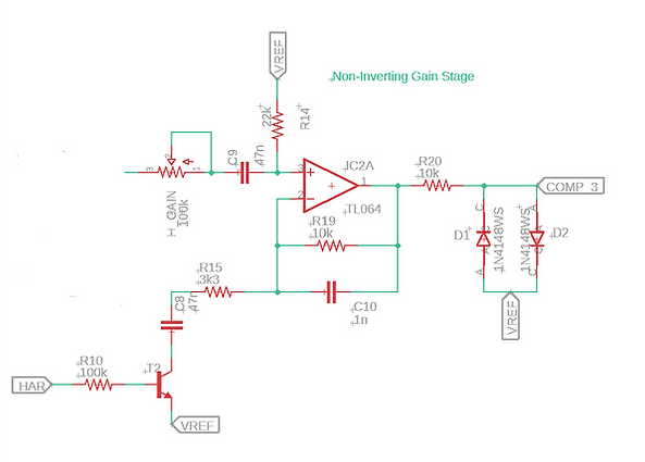
Sustainiac Stealth Variable Gain Stage
The power amplifier is actually a fascinating piece of engineering. Because the design is from 1999, the design is partly due to the state of amplifier technology at the time. The power amplifier consists of an oscillator, a dual comparator, and a half bridge amplifier. We'll look at each of these.
The oscillator is a relaxation-mode oscillator that is tuned to run at about 33 kHz, resulting in a roughly triangle shaped output signal. This is a simple, low-parts count oscillator used to drive one side of the comparator circuit.

Sustainiac Stealth Oscillator
The dual comparator is fed by the audio signal and the oscillator. With one comparator, the audio is the high signal and the oscillator is the low signal. With the second comparator, the opposite is true. What this does is it results in a series of high and low pulses on the output, resulting in a PWM output signal.
The PWM output signal is fed to a discrete half-bridge amplifier made up of two large power MOSFET's and two large reservoir caps. This power amplifier configuration represents a discrete class D amplifier, which is very power efficient and therefore helps to prolong battery life. The driver coil is driven at the X+ and X- terminals of the amplifier.

Sustainiac Stealth Power Amplifier
The system also has a buffered reference voltage. Because the reference voltage is so widely used as an AC ground as well as bias supply, having it buffered is good insurance. This is a pretty straightforward design. The voltage supply for the buffer comes from the power pin of the IC containing the opamp used for the buffer.

Sustainiac Stealth Buffered Reference Voltage
The system also includes a standby mode, which is activated when the on/off switch is flipped. The point LK is wired to the ring connection of a stereo output jack, causing it to connect to ground when a cable is plugged in. +9S is the voltage from the on/off switch, causing +9S to go to 9V when the effect is turned on. +9R is the voltage supply for all the IC's. The voltage at the point labeled PWR goes to the base of T2 for the "mute" functionality discussed earlier. The power for the IC's is filtered using a 47 Ohm and 1 uF cap for each, resulting in a low pass filter at approximately 3.3 kHz. Since the unit is battery powered the filtering isn't that important. The capacitor also acts as a filter decoupling cap/charge reservoir.
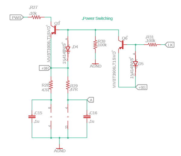
Sustainiac Stealth Power Standby Section
Finally, the system has a 10 pin header on one end. The order and meaning is as follows:
-
+9: 9V battery connection
-
X+: Driver coil + side
-
X-: Driver coil - side
-
LI: One side of the harmonic mode gain control
-
LK: Ground wired to ring of stereo output jack
-
+9S: Connected to power switch. Connects to +9 when in "on" position
-
GND: Connection to guitar circuit ground. Should go to a main ground buss
-
+9R: 9V connection, gets wired to one side of harmonic mode switch
-
HAR: Connects to other side of harmonic mode switch. Connects to +9V when enabled
-
LO: Second side of harmonic mode gain control. Can be wired to potentiometer as a variable resistor to LI, or LO and LI can simply be connected together (this is how my system came wired from the factory)
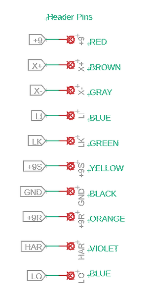
Sustainiac Stealth Header Pins
If you want to have a go at making your own, I have Gerbers and a BOM file for board that is the same size as the original. Note that it is surface mount using 0805/SOIC components. You can find them here.
Additional patent numbers that are useful for studying sustainer technology are:
-
US4941388A
-
US5070759A
-
US5932827A
-
US20020069749A1
Below are the factory wiring diagrams showing various ways of connecting the board. One thing to note from these is that the "mix" mode is actually just using a 22 uF cap in fundamental mode that slows the attack of the amplifier, resulting in what they describe as "more natural feedback onset". I've not tried it yet, though, but it's there.
Sustainiac Stealth Two Pickup, Two Pot Wiring Diagram
Sustainiac Stealth HSH Wiring Diagram
Sustainiac Stealth Mix Mode Wiring Diagram
Phil Hill from the Guitar Sustainer DIY Facebook group has created a spreadsheet calculator tool for coil winding. It allows you to change wire gauge, bobbin size, and target resistance and will calculate the number of winds to reach that target given the information. I have tested it with a few different coils and wire gauges and it has been pretty accurate. He has provided it for personal use and can be found below.