

EchoWreck
A PT2399-Based Work-Alike of the Classic Echo Machine

Overview
In a discussion of classic delay/echo effects, the ones that most frequently get mentioned are the EchoPlex EP-3, Roland Space Echo, and the Binson Echorec. The EP3 and Space Echo are tape delays, while the Echorec is based around a magnetic disk that spins past 4 playback heads.
There have been some DIY projects in the past that have attempted to replicate the sound of the Echorec with varying amounts of success. The awesome Multiplex from 1776 Effects cops the general vibe of the Echorec, but uses only two delays instead of 4. The FV-1 chip also makes it possible to get a high level of accuracy and detail, but I'm a cheapskate and wanted to see what I could do with the old standby, PT2399.
The Echorec has a fixed delay time of approximately 300 ms, but I wanted to give a little more flexibility, so I added adjustable (but synchronized) delay times and decided to add tap tempo for good measure. Additionally, there is filtering on both the playback and feedback paths.
Don't want to read all about how it works below? Go get all the project stuff you need here.
How It Works
From a very high level, EchoWreck is very similar to other popular PT2399 delays. It has an input buffer, PT2399 for delay, adjustment for mix level, and output buffer. However, instead of a single delay line, there are four in parallel. This could also be done with the delay lines in serial, but it makes the switching logic, particularly for feedback, more difficult and can result in more noise in the later repeats, which is not characteristic of the Echorec.
Toggle switches are used to control which “heads” are active and for which function. Toggles are provided for all four heads for both playback (initial echo) and feedback (subsequent repeats). There is also a toggle for “swell” mode, which really just activates all four heads for playback which, when used in conjunction with feedback, can give that big, cavernous sound the Echorec is known for. Finally, there is a toggle for the “drift” function, which currently is programmed to change the time division of the second and fourth repeats to give a bit of a “wobble” characteristic. I have coded it so that they are still rhythmically related, but feel free to change the code to make it be whatever you want.
The input buffer is a run-of-the-mill opamp buffer to prevent loading and present a high input impedance. Nothing special here.
EchoWreck Input Buffer
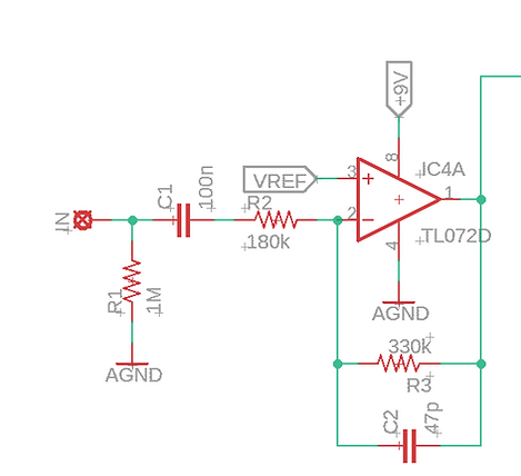
The output from the input buffer is sent to another opamp, this time configured as a summing amplifier. This sums the dry input signal with the feedback signal prior to sending the signal to the input of each delay stage. This prevents loading between the two signals so that the feedback can be dialed down to a low level without causing the overall delayed signal output level to also drop. Without it, things go bad quickly. Ask me how I know...
EchoWreck Delay Stage Input
The actual delay stages are pretty straightforward. For a detailed breakdown of what each component is doing here, visit ElectroSmash's most excellent PT2399 circuit analysis page. Just a couple of things to note are that I chose 1 nF caps between pins 15/16 and 13/14 to keep the delays bright. With the tone control, I can always remove some of that brightness, but you can't recoup it once it's gone.

EchoWreck Delay Stage, or "Head"
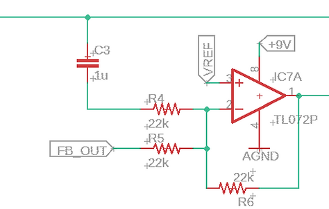
The feedback path (shown in the figure below) utilizes a summing amplifier to prevent bleed between channels. This is then fed through the Age control, which controls the amount of bass in the feedback signal. With full bass, the repeats have more low end content, like an older disk/head. With the age backed off, the feedback repeats are brighter, like on a brand new disk/head. The feedback level control is configured as it is to prevent pulling the FB_OUT signal to ground when turned to 0, which impacts the input to the delay lines.

EchoWreck Feedback Path
The output from each PT2399 is sent to an input of a CD4066 CMOS quad switch. Each switch is an SPST, controlled by the voltage on a dedicated control pin. The playback toggle switches control the voltage for the 4066 switch for each “head”. The Swell control applies the control voltage to each of the four switches, activating all four “heads”, regardless of the other toggle switch settings.
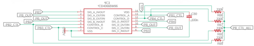
EchoWreck Playback Switching
The outputs of all four CD4066 switches are tied together and sent to an opamp summing amplifier to prevent loading and bleed between “heads”. The playback signal then goes through a tone control that can roll off highs from the playback signal to give it a “softer” feel, or give it a little bit of brightness like the Echorec is renowned for. From there, it goes into the Mix control before being combined with the dry signal at the output buffer. Note that the mix control in the figure below is shown as B50k. It can be increased to B100k to get to slightly greater than unity repeats, which I did on my personal build. It's up to you.

EchoWreck Playback Path
The output buffer is a standard output buffer that doubles as a summing amplifier for the dry and delayed signals.
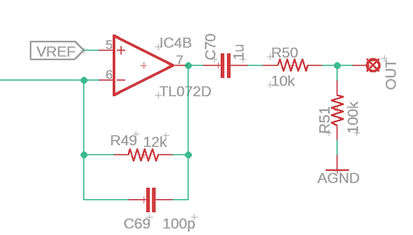
EchoWreck Output Buffer/Summing Amplifier
As mentioned earlier, the delay times are synchronized. This is accomplished by using the four PWM outputs of an ATTiny841 (NOT and ATTiny84, which only has two PWM outs). Using a lookup table that relates delay time to PWM duty cycle, the microcontroller keeps the delay times in sync by keeping track of the longest delay time and calculating the other delay times from it, then using the lookup table to set the appropriate duty cycle for each output. The PWM signal is then smoothed and stabilized using an active current sink, which is connected to pin 6 of the PT2399 to set delay time. The figure below shows what this current sink looks like. Note the use of the TLC2272, which is a rail-to-rail opamp. This current sink will NOT work with something like a TL072, since it cannot swing to the voltage rails.

EchoWreck Current Sink for Controlling Delay Time
The delay time is controlled by either tap tempo, or through turning a rotary encoder. The rotary encoder is used instead of a potentiometer so that a time can be tapped in and then adjusted from there, as opposed to a potentiometer which would override any tap setting when turned.
The power section for the EchoWreck is pretty straightforward. It uses the 9V input to create a VREF for the opamps and +5V for the PT2399, ATTiny, and CD4066. Note that decoupling caps are placed locally to all chips in the board layout.

EchoWreck Power Supply Section
So You Want to Build One?
Are you interested in building your very own echo machine? Well, luckily for you, I have complete build documentation, including schematic, Gerber files, BOM, build notes, code, and artwork available here. Head on over and check it out!